Vibration Transmission in Couplings
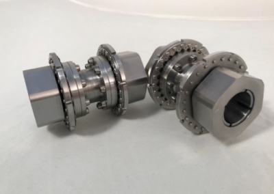
Reduce Coupling Vibration Transmission with FLEXXOR Couplings
For years, the equipment owners have lived with excessive vibration generated from gear couplings. This post helps describe why coupling vibrations happen, and more importantly, how the FLEXXOR coupling can help eliminate the vibration transmission in the coupling system.
Forces and Moments Generated by Gear Couplings
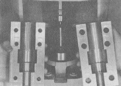
In a gear coupling the torque is carried by high local forces between the gear teeth. In order to move the coupling sleeve with respect to the hub, it must slide on the teeth. In order to slide it must overcome the friction load created by the high force between the teeth to transmit the torque. If we take as an example a size 2 ½” gear coupling transmitting 351 HP per 1,000 RPM at a gear pitch diameter of 5”, a tangential force of 8,850 lb is produced. Ignoring the effect of the tooth pressure angle, and assuming only 0.15 for a friction coefficient, then a force of 0.15 times 8,850 = 1,330 lb would be required to slide the coupling axially. This is a typical problem with gear couplings and results in a high transmission of thrust from one rotor to the other. This is commonly called coupling lock-up, and can result in thrust bearing failures. It often causes shutdown of the machines, because thrust bearing clearances are indicated by the detecting instrument as being too small. In many cases, it is considered to be advantageous to have some misalignment of a gear coupling, so that the surfaces are continually working and thereby tend to prevent this axial lock-up condition. Obviously misalignment will also cause wear of the coupling, so that this is not a desirable way to prevent lock-up.
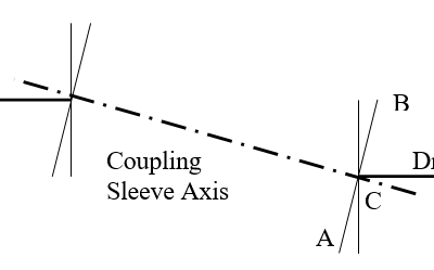
In addition to the friction causing high thrust loading in a gear coupling, it also causes high moments on the shaft end, and transverse forces transmitted from one shaft to the other. This can be illustrated by studying the diagram below, showing the position of a gear coupling sleeve with offset misalignment.
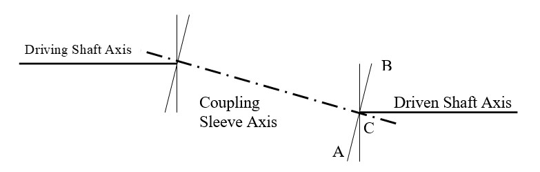
Note that point A on the coupling must move axially to point B position in one half revolution. Therefore, it must wobble from A to B and back to A in each revolution. During this cycle, the gear teeth must slide on each other. At the same time, they are heavily loaded to transmit the torque. Therefore, the angular wobble requires a force proportional to the friction required to slide the teeth under load. Since point A moves to the right and point moves to the left as they turn from the plane in view, then the friction forces create a bending moment on the joint. If we assume that the friction load is uniform around the circle, then the bending moment would occur at 90 degrees from the plane of misalignment, and would produce reactive forces at the supporting shaft and the coupling shaft.
On the diagram it is obvious that the relative axial velocity of the teeth at point A and point B is zero, and that it is maximum at C. Since the friction coefficient is higher at zero velocity than when friction surfaces are sliding it is obvious that the friction coefficient carries around the circle. Also, the tooth pressure is not uniform around the circle. At point A and B, the tooth spaces are parallel, but at point C they are not. Therefore, the tooth pressure changes. Ideally, all the teeth are perfectly machined on both the male and female gear sets so that at point A and B where the relative sliding stops and changes direction, each tooth successively imparts its portion of moment to the shaft. If there were 36 teeth for instance, and we had accurate sensing equipment, we might sense 18 small moment impulses in each revolution as the teeth at point A and B (assuming they are 180 degrees apart) break from static to sliding. Most likely, however, two teeth carry more load so there is more friction at one set of teeth (180 degrees apart) than others. Then as these teeth break free at points A and B, there is a noticeably higher moment impulse which occurs once of twice a revolution (depending of the friction force between teeth varies with direction of sliding as it might as the result of a wear pattern).
Clearly, a much higher moment impulse is felt on the shafts. This reaction may excite a natural frequency in one of both rotors, or it may force enough movement of the shaft so as to trigger proximity of vibration probes. From this discussion it is obvious that misalignment of gear couplings generates forces considerably higher than the weight of the coupling, and that are very probably variable and cyclical in nature. They are also very probably higher than unbalance forces.
The energy input per revolution is proportional to the deflection or offset misalignment. This explains why gear couplings wear out, and why they are so sensitive to misalignment. It also explains why they cause coupling vibration when misaligned, and why they transmit vibration from one shaft to the other.
Vibration Transmission Reduction
Besides the vibrations that are potentially generated by the gear coupling, there is also the issue of how the coupling reacts with the rest of the system. When there are vibrations in one of the machines, the coupling can act as a conduit to allow that vibration to travel from that machine to the other. There are many cases where a slight vibration in one machine may not be a problem by itself. However, when coupled to the other machine, a resonant frequency is excited in the secondary machine. Therefore, it is ideal to be able to insulate the two machines from vibration transmission, just like it is necessary to electrically insulate them in some cases.
A gear coupling provides a solid, steel-to-steel transmission path for vibrations. There is no spring or damper to reduce any vibrations as they pass through the coupling. Looking at the natural frequencies of the coupling, the gear coupling has a very high natural frequency, while the flexible coupling has a much lower natural frequency due to the springs.
The basic natural frequency is defined as:
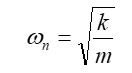
Here “k” is the coupling’s axial spring rate and “m” is the “sprung” mass, or, basically, the mass of the sleeve and other components suspended between the flexible elements of the coupling. The gear coupling, having no “spring” has an incredibly high ‘k’ value.
Having an axial natural frequency that is higher than the system’s operating speed is, in fact, quite unusual, and is most often undesirable. This is because of vibration response. Whenever possible, it is not desirable to operate below the axial natural frequency of the coupling because this increases the transmissibility of vibration. You want the natural frequency to be as low as possible so that you therefore operate as far away from it as possible. See the illustration below for an example.
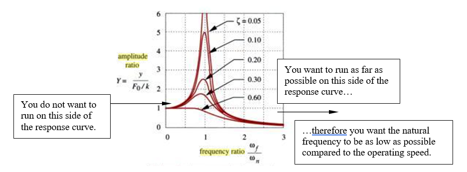
Generic vibration response curve demonstrating desirable natural frequency.
Because of its extremely high “spring” rate, the gear coupling will almost always operate in the left part of the response curve shown above. CCA’s FLEXXOR couplings will almost always operate in the far right side of the curve which allows them to reduce vibration transmission from one machine to the other.
Contact Us Today
"*" indicates required fields
Recent Posts
Runout Solution: Vertical Clamp Coupling
Lady and the Clamp
Why Machine Alignment Matters
Vibration Transmission in Couplings
I Like Big Hubs (and I cannot lie)

Circ Water Success
Surprise BSE Change
How CCA Saved a Customer Millions
FLEXXOR Coupling Reduces Vibrations in Gas Compression Application
New Year’s Resolution: Coupling Weight Loss
Downtime – Way Up in the Sky
No results found.