Circ Water Success
Large Vertical Pumps with Large Problems
Recently, a power plant had problems with its circulating water pump system. The system was rated at just over 5000 HP, running at 350 RPM. There were some vibration issues along with some other reliability issues. After studying the problem, the engineering staff determined that a significant part of the problem was a lack of stiffness in several parts of the system, including the motor stand and the 20-foot-long pump shafting. It became clear that the circulating water pump coupling was a big part of the problem, even though it had no issues. While the plant staff focused on upgrading the motor stand and a new slate of sensors to monitor the system, CouplingCorp worked on designing a new coupling for the motor-to-pump shaft connection and the line shaft coupling above the pump impeller.
Initially, the system was designed with couplings that used sliding fits on the shaft and axial and radial keys. With this type of design (and most vertical coupling designs), there is a certain amount of clearance between the coupling bores and the shafts. With the total length between the motor and the impeller being over 20 feet, any slight movement at the coupling joints caused a large radial displacement at several points.
Line Shaft Coupling
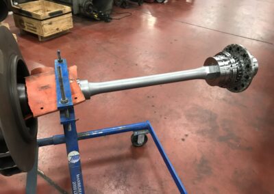
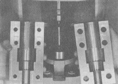
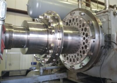
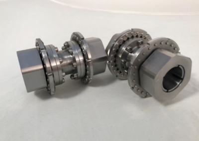
For the line shaft connection, CouplingCorp designed a Vertical Line Clamp coupling with loading screws at each end. The coupling was built using 17-4 stainless steel to handle being submerged as well as being in the flow path of the water. The design allowed the plant to install the coupling at the bottom of the line shaft while lying on the ground. Before sliding the coupling onto the shaft, the shaft keyways were fitted with half keys to fill the void.
The mechanics, who were using this technology for the first time, learned the clamping procedure and had it fully clamped in less than 30 minutes. Once tightened, the whole shaft was lifted and then dropped down into position on the top of the impeller shaft. Then, the bottom half of the Line Clamp Coupling was tightened in place. See the pictures below. For a video of the whole installation process, click this video button below.
-
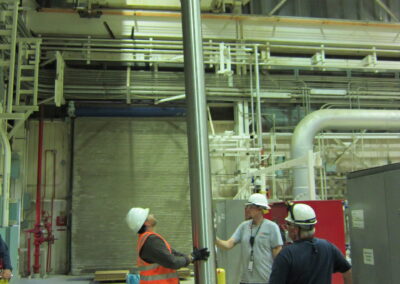
Circulating water pump coupling installed on the bottom of the shaft
-
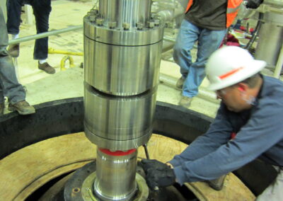
Clamping the bottom of the line shaft coupling in place above the impeller
Motor to Vertical Pump Coupling
Once the line shaft and impeller were lowered into the pit, installing the Vertical Clamp Coupling between the motor and line shaft was next. With the new sensors added inside the motor stand, the coupling had additional features to help get reliable readings. Consequently, there were some burnished bands on certain parts of the coupling for the proximity probes, and a timing notch was added for the key phasor to monitor speed.
Because the plant was also installing a new motor stand at the same time, there was some worry about being able to predict the distance between shaft ends accurately. For this reason, CouplingCorp designed the Vertical Clamp Coupling so that either the top or bottom hub could be loosened and re-tightened while the coupling, motor, and pump were in place. This feature would allow the plant to make up for a change in the distance between shaft ends – either shorter or longer. More importantly, this could be done without having to move or shim the motor.
-
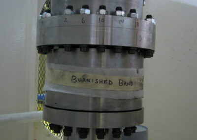
Burnished area of the circulating water pump coupling for accurate sensor readings
-
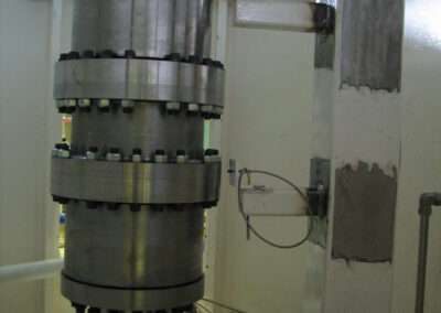
Complete vertical pump coupling installed inside the motor stand
The installation went very well despite being the first time using this type of vertical pump coupling. The plant subsequently installed the same Vertical Line Clamp and and Vertical Clamp Coupling on their other circ water pumps.
Contact Us Today
"*" indicates required fields
Recent Posts

Lady and the Clamp
Why Machine Alignment Matters
Vibration Transmission in Couplings
I Like Big Hubs (and I cannot lie)

Circ Water Success
Surprise BSE Change
How CCA Saved a Customer Millions
FLEXXOR Coupling Reduces Vibrations in Gas Compression Application
New Year’s Resolution: Coupling Weight Loss
Downtime – Way Up in the Sky
