Lady and the Clamp
When an LNG plant has multiple compressors driven by GE MS7001 gas turbines, it can be a fairy tale romance. But, when the evil villain, in this case, a hydraulic hub, gets involved, it can put the whole story in jeopardy. Over the years of operating, this LNG plant had several transient torque incidents. Unfortunately, some events caused their coupling hubs to slip on the compressor shafts. The plant and the compressor searched for a hero to give this story a happy ending.
Hydraulic Hub Problems
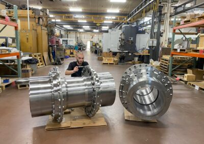
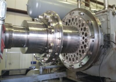
The Frame 7 gas turbines put out 122,000 HP (90MW) at approximately 3600 RPM. This equates to a normal torque of 2.14 million in-lbs (242,000 Nm). The compressor shaft had a diameter of 10.2 inches (260mm) with a 1:20 taper (0.60 in/foot). The hydraulic hub had a slip rating of 4.72 million in-lbs (534,000 Nm).
Hydraulic Hub Destroyed During Removal
When the various transient torque events occurred, the hydraulic hub would slip on the shaft in some cases. Sometimes, it was evident immediately, although other times, it was unknown until it was time for hub removal. If the hub had slipped during operation, there was typically some shaft damage, which made it more difficult to remove. Commonly, when hydraulic hubs are stuck, brute force and/or destruction can be the only ways to remove them.
Of course, the damaged hub is only one part of the problem because the damage to the tapered compressor shaft can be even more of a concern. In each case, the plant personnel had to make a difficult decision if it was safe to reuse a shaft that had some damage or, have it refurbished, or, in the worst case, throw it away. If they decided the damage was minimal enough to reuse the shaft, the risk of a future hub slip rises.
Anderson Clamp Hub to the Rescue
The corporate engineering group set out to find a hub solution that would provide a higher torque transmission capability. The new hub also had to work on shafts that already had some damage. In addition to its performance characteristics, it also had to have the same weight and inertia as the original hub so that the system’s dynamics would be preserved.
After significant research, the company came to Coupling Corp to learn about the Anderson Clamp Hub, and how it might perform in this critical application. First, they wanted to understand the stresses in the Clamp Hub and how they relate to the clamping pressures. Once they were satisfied with the design on paper, they requested that Coupling Corp perform some bench tests on a full-size hub to prove that it could perform in even the worst-case situation. So, Coupling Corp designed a testing strategy and process to prove the capabilities.
Clamp Hub Testing – To the Max
There were three primary phases to the testing after building a full-size Anderson Clamp Hub and a test shaft. The first phase was to show the installation and removal process under normal conditions combined with a full torque test at regular loads and up to peak loads. The second phase was to be a check of the hub performance if load screws were loose or even missing. The goal of the last phase was to show how the hub would work on a damaged shaft, just like it might do in the actual application.
Clamp Hub Test Phase 1 – Standard Conditions
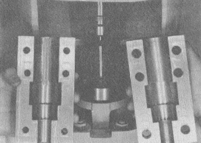
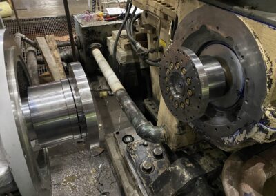
The corporate engineering group sent a representative to witness all testing and get a good understanding of the clamping and unclamping process. In the first set of tests, the Anderson Clamp Hub was installed and fully loaded on to the test shaft. The hub and shaft assembly was bolted into place on CouplingCorp’s large static torque tester. The nominal torque capacity of the Clamp Hub was 2.57 million in-lbs (290,000 Nm), so that was the first level of torque test. After reaching that milestone with no issues, the torque tester increased the level to the peak capacity of the Clamp Hub, which was 3.9 million in-lbs (440,000 Nm). The hub still showed no signs of moving.
With success at those levels, the technicians increased the torque as high as possible without breaking the flange bolts. The torque grew to 4.6 million in-lbs (520,000 Nm), and there was still no sign of slipping on the shaft. After that, the hub was removed from the test shaft using the standard unclamping process. After testing, inspection of both the test shaft and the Clamp Hub bore revealed no marking or deformations.
Clamp Hub Test Phase 2 – Missing Load Screws
The second testing phase was to perform a similar test regiment to the first with one exception. With the Clamp Hub fully clamped, 3 of the 18 pushing bolts were removed. This was an effort to prove that the hub would work even if the installation were done incorrectly. The torque tester was pressurized to create the nominal torque, and there was no hub slip. Then it was increased to the peak level, and there was still no slip. Finally, it was increased to the max testing value of 4.6 million in-lbs, and again, there was no slippage. The Clamp Hub passed the test to carry the entire load.
After the torque test, the Clamp Hub was unclamped, and the bore and shaft were rechecked for any damage. They were clear of any problems. Also, the loading screws adjacent to the missing loading screws were carefully inspected to see if they showed any signs of being overloaded. They did not show any signs of over-stress.
Clamp Hub Test Phase 3 – Damaged Shaft
The final test was designed to mimic the worst-case scenario found in the field – a damaged shaft. A damaged shaft might normally have scratches, gouges, galling, or other surface abrasions. When such damage occurs, cleanup can be achieved using sandpaper, stones, or even some grinding mechanism. With any of those methods, there is a risk of causing the shaft to lose its roundness. It is also likely that the shaft will have low spots – especially if there was a significant gouge. This type of damage is problematic for hydraulic hubs because it makes it harder to create pressure in the bore.
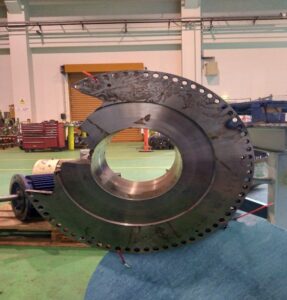
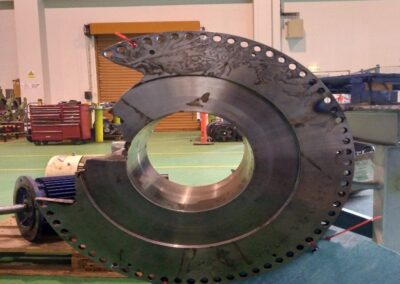
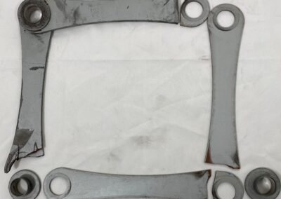
Test shaft after milling away 30% of the tapered surface
To test the Anderson Clamp Hub on the damaged shaft, the test shaft had to be “damaged.” The customer decided that a 30% reduction in surface area was an extreme but logical value to use for the test. So, the test shaft was machined so that 30% of the surface area was removed.
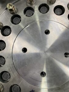
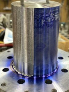
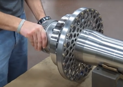
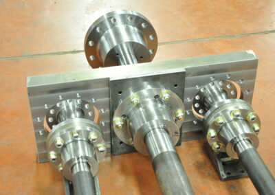
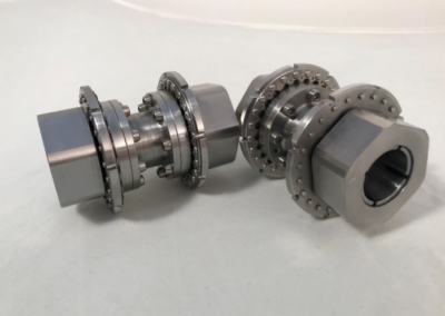
Anderson Clamp Hub on the test shaft with 30% surface reduction
The pictures show the shaft after machining (the area where the blue is removed). Then, the Clamp Hub was installed like usual, and it was easy to see the gap between the hub bore and the shaft. See the picture below.
After loading the hub, the assembly was bolted on to the torque tester, and the same tests were performed. Like before, there was no movement at the normal torque or the peak torque. But would the hub be able to hold to the max testing torque without slipping? The pressure built up in the torque tester, and the torque climbed to the 4.6 million in-lb limit with no slipping!
Fairy Tale Ending
With the highly successful testing complete, the customer ordered a new Anderson Clamp Hub to be installed on the actual compressor. Once that unit was installed and running well for many months, the plant ordered and installed Clamp Hubs for the rest of the compressors in the plant. These installations also pushed them to install Anderson Clamp Hubs at other LNG plants. Fortunately for the gas turbine and the compressor, the villain was removed from the story and replaced with the hero – the Anderson Clamp Hub – and they all lived happily ever after.
Contact Us Today
"*" indicates required fields
Recent Posts
Runout Solution: Vertical Clamp Coupling
Lady and the Clamp
Why Machine Alignment Matters
Vibration Transmission in Couplings
I Like Big Hubs (and I cannot lie)
Circ Water Success
Surprise BSE Change
How CCA Saved a Customer Millions
FLEXXOR Coupling Reduces Vibrations in Gas Compression Application
New Year’s Resolution: Coupling Weight Loss
Downtime – Way Up in the Sky
No results found.